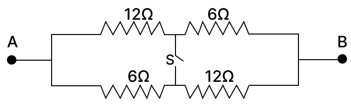
(a) When the switch is open, the middle connection does not join the two branches. So the circuit has two separate branches in parallel i.e., top and bottom branches where 12 Ω and 6 Ω resistances are in series.
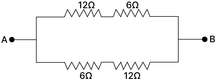
Then net resistance of the top branch is given by,
$\text R_1 = 12 + 6 = 18 Ω$
Similarly, net resistance of the bottom branch is given by,
$\text R_2 = 12 + 6 = 18 Ω$
Now, $\text R_1$ and $\text R_2$ are in parallel connection and the net resistance is given by,
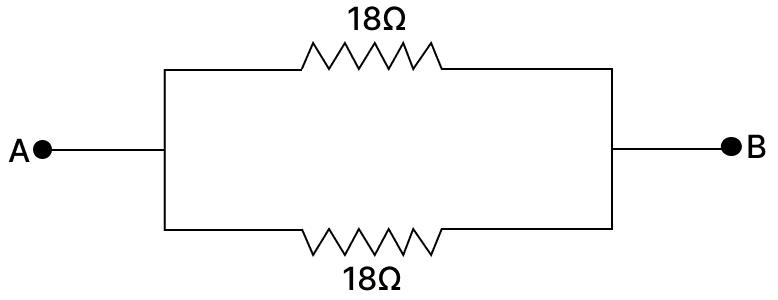
$$\begin{aligned}\frac{1}{\text R} = \frac{1}{\text R_1} + \frac{1}{\text R_2} \\[1em] = \frac {1}{18} + \frac {1}{18} \\[1em] = \frac {2}{18} \\[1em] \Rightarrow \frac{1}{\text R} = \frac {1}{9} \\[1em] \Rightarrow \text R = 9\ \text Ω\end{aligned}$$
Hence, the resistance across AB when the switch S is open is 9 Ω.
(b) When switch S is closed, the midpoints are connected which rearranges the circuit into two branches of parallel resistors that are connected in series as shown below.
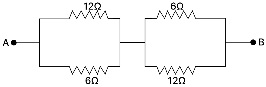
Then net resistance of the left branch (containing 12 Ω and 6 Ω resistances) is given by,
$$\begin{aligned}\frac{1}{\text R_1} = \frac{1}{12} + \frac{1}{6} \\[1em] = \frac {1}{12} + \frac {2}{12} \\[1em] = \frac {3}{12} \\[1em] \Rightarrow \frac{1}{\text R_1} = \frac {1}{4} \\[1em] \Rightarrow \text R_1 = 4\ \text Ω\end{aligned}$$
Similarly, net resistance of the right branch (containing 12 Ω and 6 Ω resistances) is given by,
$$\begin{aligned}\frac{1}{\text R_2} = \frac{1}{12} + \frac{1}{6} \\[1em] = \frac {1}{12} + \frac {2}{12} \\[1em] = \frac {3}{12} \\[1em] \Rightarrow \frac{1}{\text R_2} = \frac {1}{4} \\[1em] \Rightarrow \text R_2 = 4\ \text Ω\end{aligned}$$
Now, $\text R_1$ and $\text R_2$ are in series connection and the net resistance is given by,

$$\begin{aligned}\text R = \text R_1 + \text R_2 \\[1em] = 4 + 4 \\[1em] = 8\ \text Ω\end{aligned}$$
Hence, the resistance across AB when the switch S is closed is 8 Ω.