Integrating Robots as a System

ICSE Class 10 Robotics & AI · KIPS Robotics & AI · 26 solved questions

Exercise
1Activity 6.1

What would be the status of LED in this circuit at Tinkercad?
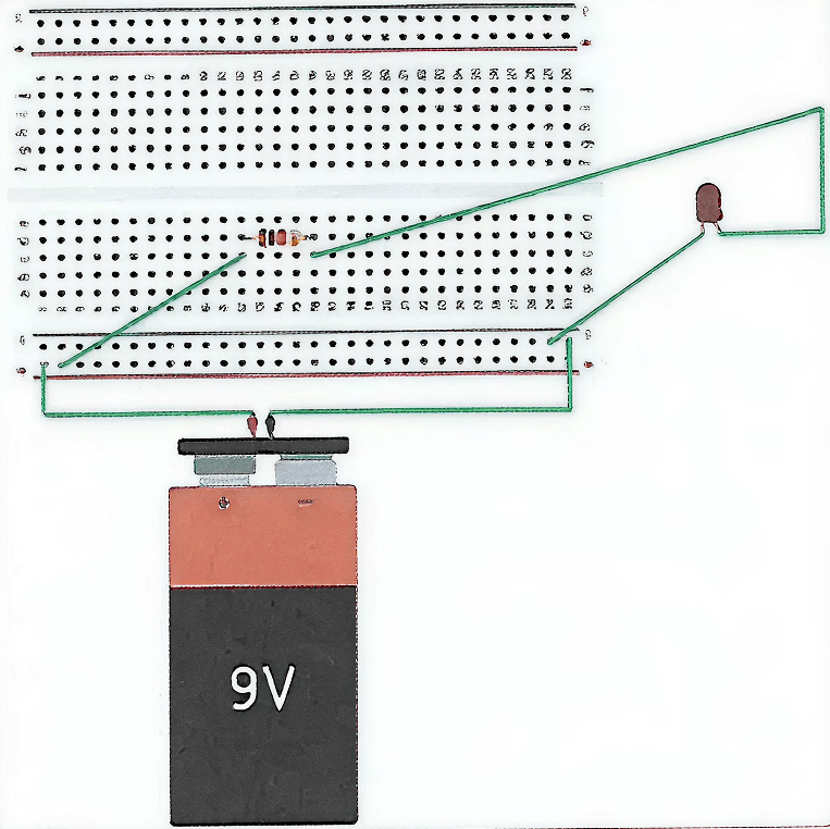
What would be the status of LED in this circuit at Tinkercad. Integrating Robots as a System, KIPS ICSE Robotics & Artificial Intelligence Solutions Class 9.
Show SolutionHide Solution↓

The LED will glow in this circuit at Tinkercad.

Explanation
In the given circuit, the 9 V battery is connected to the breadboard such that one rail acts as the positive terminal and the other rail acts as the negative terminal. The LED is connected in series with a resistor between these two rails. Therefore, a closed circuit is formed:

Battery (+) → Resistor → LED → Battery (–)

Since the circuit is complete, current flows through the LED in forward bias, so the LED glows. The resistor is used to limit the current and protect the LED from damage.
1Activity 6.2

Find out about other motors available at Tinkercad that can be used to design a wheeled robot.

Show SolutionHide Solution↓

Apart from DC motors, other motors available in Tinkercad that can be used to design a wheeled robot include servo motors and stepper motors, which can also be used for controlling motion in robotic systems.

1Activity 6.3

What are the input and output pins on an Arduino board?

Show SolutionHide Solution↓

On an Arduino Uno, the pins used to connect external components are mainly input and output pins.

  • Input pins take signals into the Arduino from devices like sensors, switches, and buttons.
  • Output pins send signals from the Arduino to devices like LEDs, buzzers, and motor drivers (as HIGH = 5V or LOW = 0V).
    The Arduino Uno has digital I/O pins (D0–D13) and analog input pins (A0–A5). Some digital pins also provide PWM output for speed/brightness control.

Pin Table (Arduino Uno)

Pin TypePin Numbers (All)Use / Note
Digital Input/OutputD0–D13Can work as INPUT or OUTPUT (set using pinMode).
Analog InputA0–A5Used to take analog sensor input. (Can also be used as digital pins D14–D19.)
PWM Output PinsD3, D5, D6, D9, D10, D11Give PWM output (analog-like output) for motor speed / LED brightness control.
Serial Communication PinsD0 (RX), D1 (TX)Used for serial data transfer (USB communication).

Power pins like 5V, 3.3V, GND, Vin are not I/O pins; they are used only for power connections.

1State True or False

The breadboard is used to manage multiple connections in a circuit.

Show SolutionHide Solution↓

True

Reason — A breadboard is used to connect multiple components and manage multiple connections in a circuit, as it provides several internally connected points for making circuit connections easily.

2State True or False

DC motors are used to move the wheel of the robot.

Show SolutionHide Solution↓

True

Reason — DC motors act as actuators in a robot and are used to move the wheels of the robot.

3State True or False

In general, black terminal of motors shows the connection with the motor driver.

Show SolutionHide Solution↓

False

Reason — In general, the black terminal of a DC motor is connected to the ground of the microcontroller, while the other terminal is connected to the output of the motor driver.

4State True or False

Controller is the brain of robot.

Show SolutionHide Solution↓

True

Reason — The controller generates all the controlling signals of the robot through a program and controls the working of all components, hence, it is considered the brain of the robot.

5State True or False

It is not essential to use motor driver.

Show SolutionHide Solution↓

True

Reason — A motor can rotate as long as it gets a suitable power supply, so a motor driver is not strictly mandatory just to make the motor run. However, a motor driver acts as an interface between the controller (Arduino) and the motors, helps in controlling the motor, and provides enhanced current capacity because directly connecting a motor to the Arduino can damage the Arduino or reduce motor performance.

6State True or False

Motor driver is connected in between controller and motor.

Show SolutionHide Solution↓

True

Reason — The motor driver acts as an interface between the controller (Arduino Uno) and the motors. It is connected in between them to control motor movement and to supply the required current to the motors based on the signals received from the controller.

7State True or False

Arduino uno has only input pins.

Show SolutionHide Solution↓

False

Reason — Arduino Uno has both input and output pins.

8State True or False

In forward mode, only one wheel of the robot should be in motion.

Show SolutionHide Solution↓

False

Reason — In forward mode, all the wheels of the robot should be in motion. Therefore, HIGH values are sent to all four output pins of the Arduino so that all four motors run together and the robot moves forward.

1Select the correct option

Arduino Uno is a ............... .

Show SolutionHide Solution↓

Microcontroller

Reason — Arduino Uno is a microcontroller that acts as the controller or brain of the robot.

2Select the correct option

Breadboard is a ............... .

Show SolutionHide Solution↓

Connecting device

Reason — A breadboard is used to connect multiple components in a circuit and provides several internally connected points, making it easier to manage and organise circuit connections.

3Select the correct option

The HIGH value indicates the motor has received ............... .

Show SolutionHide Solution↓

5V

Reason — HIGH indicates that the motor driver will receive 5V, and the same value will be transferred to the motor with enhanced current capacity.

4Select the correct option

Motor in robot work as a/an ............... .

Show SolutionHide Solution↓

Actuator

Reason — Motors are the actuators of the robot. They are used to move the wheels of the robot.

5Select the correct option

The ............... pin is used to give ground connections to the motors that are going to control the wheels of the robot.

Show SolutionHide Solution↓

GND Pins

Reason — The GND pin is used to give ground connections to the motors that control the wheels of the robot and is also connected to the ground pins of the motor driver IC.

6Select the correct option

Number of pins on Motor driver IC, L293D is ............... .

Show SolutionHide Solution↓

16

Reason — The motor driver IC L293D has 16 pins.

7Select the correct option

Task of digitalWrite() function is ............... .

Show SolutionHide Solution↓

Give input to Arduino

Reason — The digitalWrite() function is used to send input to the Arduino by writing HIGH or LOW values to the digital output pins.

8Select the correct option

The role of enable pin in motor driver IC is ............... .

Show SolutionHide Solution↓

To enable its working

Reason — Without enabling the enable pins, the motor driver will not work. Therefore, the role of the enable pin in the motor driver IC is to enable its working.

1Fill blanks

Fill in the blanks:

Show SolutionHide Solution↓
  1. Motors are used to move the wheels of the robot.
  2. Motor Driver L293D has four input pins.
  3. 5V pin in Arduino is used to provide a power supply of 5V to other components.
  4. Delay function takes input in milli seconds.
  5. In forward mode, all the output pins receive high values.
1Short answer type questions

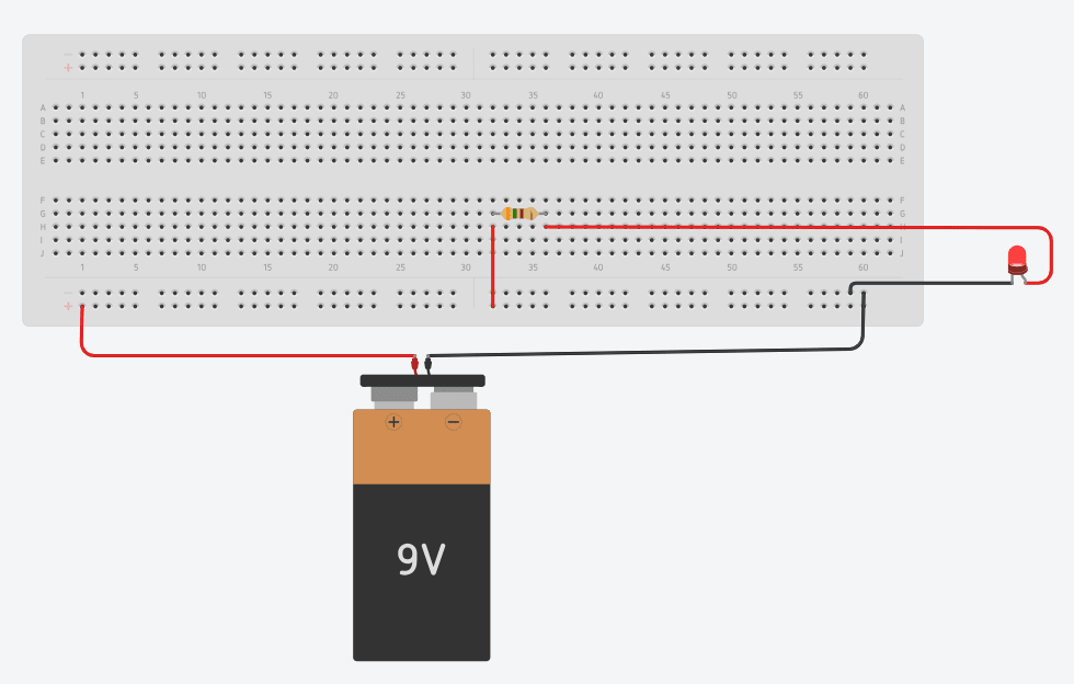
With the help of the battery, make the connection to glow an LED.

Show SolutionHide Solution↓

The Tinkercad connection to glow an LED with the help of the battery is shown below:

With the help of the battery, make the connection to glow an LED. Integrating Robots as a System, KIPS ICSE Robotics & Artificial Intelligence Solutions Class 9.

The value of resistor is 350 Ω

2Short answer type questions

Explain the use of digitalWrite() function.

Show SolutionHide Solution↓

The digitalWrite() function is used to control the state of a digital pin on the Arduino microcontroller. It is used to send a HIGH or LOW signal through an output pin.

  • HIGH means the pin outputs 5 V (ON)
  • LOW means the pin outputs 0 V (OFF)

Syntax:
digitalWrite(pin, value);
Where pin = digital pin number, and value = HIGH or LOW.

Example:
digitalWrite(3, HIGH);
will send a HIGH signal through pin 3

3Short answer type questions

Explain the structure of breadboard.

Show SolutionHide Solution↓

A breadboard is a device used to connect multiple components in a circuit. It provides multiple connection points that are internally connected. In a breadboard, the first two and the last two lines are horizontally connected, while in the remaining two blocks, the connections are vertically connected. These internal connections help in making circuit connections easily without soldering.

1Long answer type questions

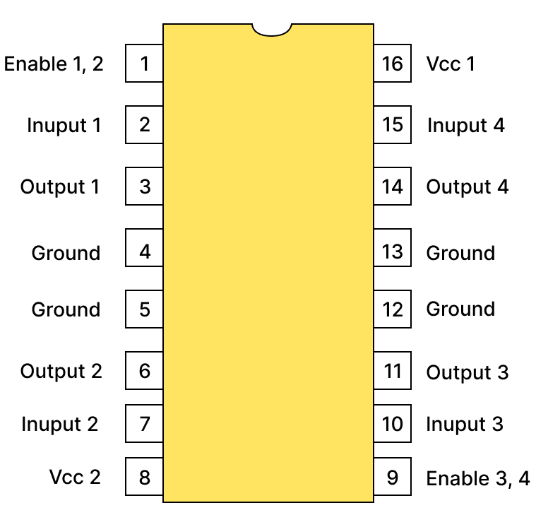
Make the labeled pin out diagram of motor driver.

Show SolutionHide Solution↓

Labeled pin out diagram of motor driver is shown below:

Below image is representing Components of Visualisation, Design, and Creation of Components, KIPS ICSE Robotics & Artificial Intelligence Solutions Class 9.
2Long answer type questions

Explain forward move of wheeled robot.

Show SolutionHide Solution↓

In the forward move of a wheeled robot, all the wheels of the robot should be in motion. For this purpose, a HIGH value is sent to all four output pins (3, 5, 6, and 9) of the Arduino Uno. When HIGH is sent, the motor driver receives 5V, and the same value is transferred to the motors with enhanced current capacity. As a result, all four motors turn on, and the robot moves in the forward direction. The code for move forward is given below:

void move_forward ()
{
    digitalWrite(3, HIGH);
    digitalWrite(5, HIGH);
    digitalWrite(6, HIGH);
    digitalWrite(9, HIGH);
}
3Long answer type questions

Explain right and left move of wheeled robot.

Show SolutionHide Solution↓

Left Move:

To give left movement to the robot, its right wheels should be stopped, and left wheels should be in motion. For this purpose, LOW values are sent to pins 3 and 5, and HIGH values are sent to pins 6 and 9 using the digitalWrite() function. As a result, the right-side wheels stop moving, and only the left-side wheels move, giving the robot a left-hand move. The code for left turn is given below:

void turn_left()
{
    digitalWrite(3, LOW);
    digitalWrite(5, LOW);
    digitalWrite(6, HIGH);
    digitalWrite(9, HIGH);
}

Right Move:

To give right movement to the robot, its left wheels should be stopped, and right wheels should be in motion. For this purpose, HIGH values are sent to pins 3 and 5, and LOW values are sent to pins 6 and 9. Consequently, the left-side wheels stop, and only the right-side wheels move, giving the robot a right-hand move. The code for right turn is given below:

void turn_right()
{
    digitalWrite(3, HIGH);
    digitalWrite(5, HIGH);
    digitalWrite(6, LOW);
    digitalWrite(9, LOW);
}

Press ↓ to reveal a solution and move to the next question. Back to KIPS Robotics & AI.

Free sample bank